sailboat electrics

an area that puzzles many but critical to effective power consumption with todays cruising catamarans. Can you be self-sufficient?

Green Power

elec10

‘Green power’ is climbing up the priority ladder to such an extent nowadays that some predictions of fossil fuel costs (scorned at a few years ago), are coming home to roost.

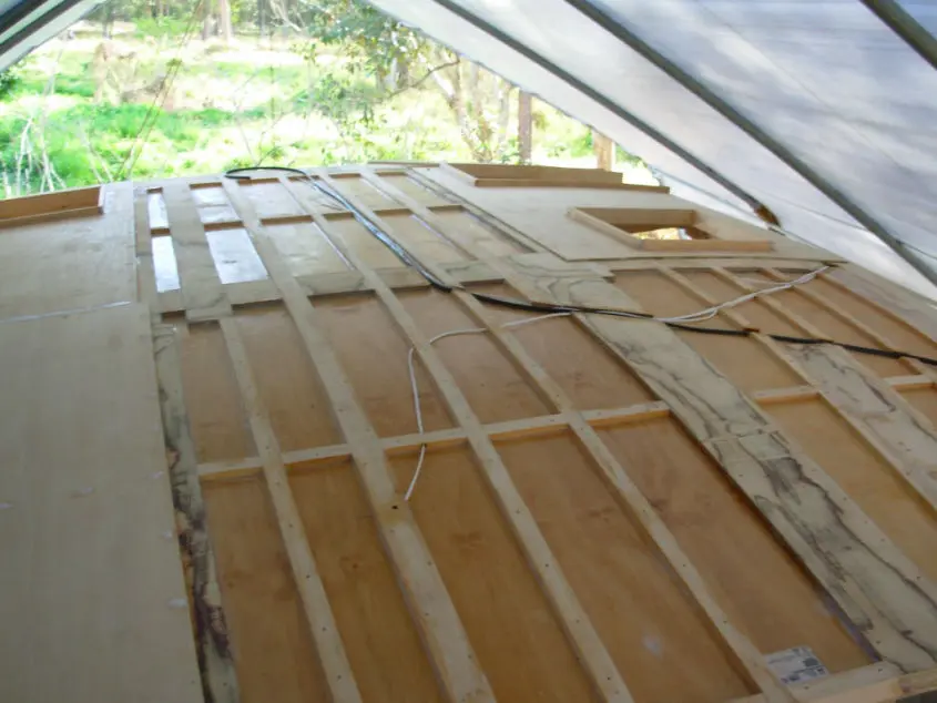
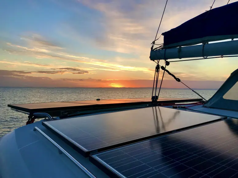
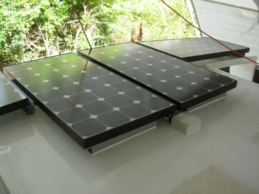
We have chosen to be proactive and endeavour to be as reliant as possible on solar power as we possibly can. Our yacht carries a few more items such as additional solar panels and batteries which will surprise some and be talked down by others.

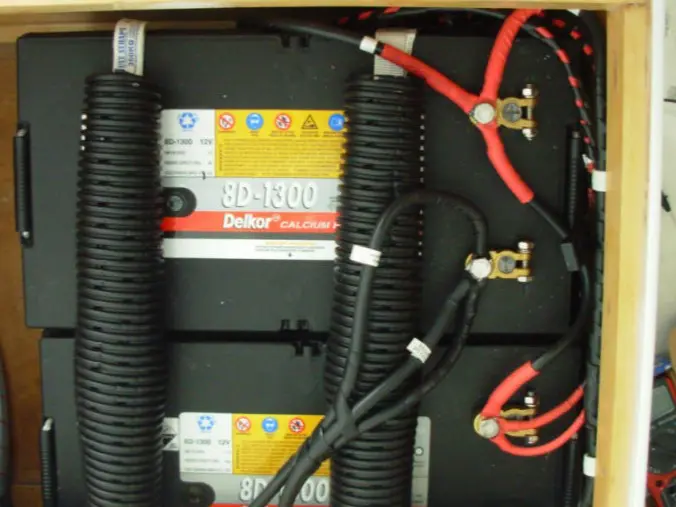
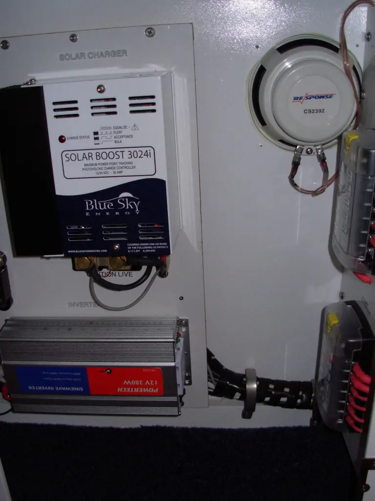
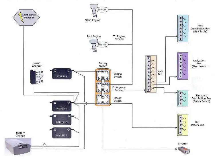
The electrical system has Solar Panels developing sufficient energy to charge three of the four Batteries to provide 12Vdc power to the vessel. Before embarking on its make-up a few things need to be clearly understood.


There is a reason that the Electrical Trade is a 4-year course in most countries and one can't read a 2-page document and be versed on all-things-electrical.

For the 'purists-in-electrical-know-how’, this may not be for you as there are phrases and words used here which may not be strictly correct in the your eyes.

We also strongly recommend that a qualified electrician be used in the connection of your vessels appliances. Your State legislation may require certification for systems over a certain voltage (or amperage) and some Insurance companies carry caviats against DIY Electrical.


Replenishment Risk

Replenishing energy (electricity) purely with proven techniques of small vessel power generation, comes with some form of ‘calculated risk’. A genuine decision has to be made on what we were going to use the boat for as this dictated the requirements and then build that into this 'Replenishment Risk'.

The most common forms of power generation on yachts include solar panels, generator/s (separate portable generator units), alternators (units making power from available and/or separate motors, usually the motors powering the boat), wind generators and water generators.


Why is it that one cannot locate a generic electrical system/diagram that can be used for their own electrical system on a boat? Its simple - 'Ask a butcher ‘how to plan Christmas day’. They could easily sell cuts of meat and sausages, but would have no idea on presents to buy, who to invite, ovens to use or even how to make a Christmas cake.

In the same way, each boat is different and all electrical setups are different and require different needs.

To calculate the initial electrical budget we jotted down all the components (including wiring) and tried to get an accurate honest figure. The result was not good. We bit our tongues and started to cut-down, after-all this was a yacht being built on a budget. It was either this, or build a bigger yacht to carry the energy and energy-makers.

elec06


"There is a reason that the Electrical Trade is a 4-year course in most countries"

Power Requirement Matrix

So, where do you start?

A 'Power Requirement Generator' (a simple Excel spreadsheet we made) allowed us to quickly change and modify (or more correctly, teach us) how to conserve energy and make best use of the power throughout the various parts of the day.

More importantly, the Electrical Matrix (another Excel spreadsheet with a list of appliances with their associated volts, amps and wattage), gave us the power needed to meet our newly planned energy budget during various times of the day.

A good example can be found in our book 'A Sailing Catamaran Building Adventure'.

elec09

A clear understanding of Basic Electrical Jargon has saved many hours of frustration in problem-fixing.

One of these understandings was the vessel power voltage of 12V DC over 24V DC, as many more appliances and components are available that utilise 12V, lowering building costs.

We jotted down everything that we thought would require power, even if it sounded silly and then went through a process of illumination, coming up with a ‘U-beat-wish-list’.

We say ‘wish-list’ as this is normally well over the top and some severe culling was required.

The advantage with 12vDC or 24vDC (in Australia), is that they do not require 'electrical certification' for the amateur builder. Other voltages need to be checked.


elec08

Bus Bars and Busses

So, what is a BUS BAR? A BUS BAR is a point of distribution, normally made out of a good power conductor, most commonly copper. Units are sometimes made from copper pipe however, in all instances, the greater the surface area for heat dissipation, the better.

In our build, we mainly utilise these on the negative side, providing a single (appropriately sized) cable directly to the negative side of the battery. In these lines there are no fuses/circuit breakers and also no switches. The positive side Bus Bars are the purpose built ‘Switch Units’ with their linked fuses/circuit breakers. We are no specialists in electrical design but have had our Bus Bars checked and rated for the ‘amperage’ given their dimensions and hole positions.

Or ‘best amperage guess’ fell within that calculated as ‘maximum rated’ and we deducted and additional 25% for peace of mind. We made two types, one to be used at the Main Bus point and the second smaller one to be used at the Nav station both rated at 300Amps for our 12vDC system. An abridged version of our 12vDC Electrical Diagram from our Books is shown below. Their names derived by the type of bus and position of the bus. We also made our own no-nonsence busbar, check out our Boatbuilding Videos, its in there.


It needs to be remembered that the manufacturer panel specifications are there either as a regulatory requirement and display optimum qualities of the product

How many Busses should you have?

elec20

We ended up with 5 main Busses:

  1. Hot Battery Bus (or HBB) - linked directly to the battery and can be left on to certain essential switchable components at all times,
  2. Main Bus ('THE MAJOR BUS') - where all the yachts DC electrical busses and DC electrical cables have their source – except the HBB above,
  3. Starboard Distribution Bus - distribution point for all DC starboard electrical,
  4. Port Distribution Bus - distribution point where a majority of the port electrical DC, Nav bus power, radios, hot water system and ships pumps have their source, and finally
  5. Navigation Distribution Bus - distribution point for all the navigation gear.

Solar Panel Make-up

The electrical items (from the Electrical Matrix) were then placed into AC and DC power requirement sections.

In our 'plot' it calculated that we needed 111 Ahrs (excluding the desalinator) or 151 Ahrs (including a small 12Vdc electric type desalinator) to cover the type of set-up we needed for each day (over a 24-hour period). And yes, this figure is relatively high when compared to other yachts persons. We say, “our boat not yours”.

Puremajek will be using four panels as opposed to one very large or even two large panels. The reasons here are:

> Our power requirements,

> Redundancy, and importantly

> Allowing the larger spread of panels over the surface, reducing the 'shadow effect' caused by sails, masts and even sun position.

Most solar cells are made up of silicon which becomes the conductor in the cell. To this, other semiconductor layers are added. Small amounts of electric current are then extracted from the cell once day-light excites their electric field.


elec05

Silicon cells are commonly made-up under the headings of monocrystalline, polycrystalline and amorphous. Also included now days on most panels are Blocking Diodes and Bypass Diodes and they have two totally different jobs to do.

It needs to be remembered that the manufacturer panel specifications are there either as a regulatory requirement and display optimum qualities of the product or there to cover litigation issues.

The implications of this are enormous, as the true figures for those days where temperatures above 25 degrees Celsius have to be addressed by you and I.

Smart Chargers

...good money on the quality solar panels and batteries, it would be very silly to rely on a cheap Smart Charger"

Understanding Solar Panels

elec01

Careful assessment of the efficiency of a solar panel and contributing power generation factors should soon ring a bell. Having said this, we planned worst case when sizing components such as the cabling and Smart Charger.

There are unusual factors such as cloud-edge-effect that can momentarily spike the generation system every now and then, and these worst case buffers need to be built in.

The panels we chose to use were monocrystalline 90W.

Understanding the panels specifications can be a little tricky and is simplified on a single diagram in our A Sailing Catamaran Building Adventure Book. Voltage and/or amperage requirements vary with solar panel make-up and this is directly related to the way the panels are connected together.

Puremajek's panels are wired in parallel (following the manufacturers specification recommendation), then run via two 25.7 mm2 copper conductor cables (one positive and one negative), reducing the cable numbers in the turret cavity from eight to just two, down 8.5m to the battery via the Smart Charger (or controller).

This provided the best resolve as should we wish to wire the panels in series (at a later stage), or even series and parallel, the cabling is taken care of for the worst case scenario.

The argument of extra weight in the cable, we found to be overstated and just that...an argument.

Having now spent good money on the quality solar panels and batteries, it would be very silly to rely on a cheap ‘Smart Charger’.

The Smart Charger (which has many other names, Intelligent Regulator, solar charger, solar regulator etc) regulates the flow of charge to the batteries and at the very least, should contain a three stage battery charge regulation.

Many have other options such as over voltage protection, reverse current protection, auto discharge functions and trickle charge functions, all geared to make life easier.


elec02


Charging and Voltage Drop

Given technology today, 3-stage charging is the least that one should source.

Temperature compensation forms a critical part of correct charging and maintaining optimum performance of ones Smart Charger, especially in climates outside 20 – 30 degrees Celsius. Why this does not form part of the unit, is beyond us. As an extra, they can be bought and wired into the system, which is what we have done.

In wiring there is a situation called Voltage Drop which is the drop in voltage verse the length/thickness of the cable (or copper conductor to be precise).

They say that Voltage Drop should not exceed 2% in a good 12Vdc system. Using the Australian AS3000 calculator, the expected Voltage Drop in our case will not exceed 1% (or 0.1V from 17.7Vmp).

One may start with 14V and by the time it reaches an appliance it may be as low as 9V, which in turn makes the appliance strain and even falter.

This drop is calculated by some using Ohms Law (which in summary says that Volts = Resistance in Ohms x Current in Amps) and this is the ‘pure way’ to mathematically understand and explain voltage (or in our case, Voltage Drop).

However, this comes with one big flaw and that is that the result is based a perfect 20 degree Celsius environment and as one could imagine, this will definitely not be the case in the turret or vessel wall cavity.

Our voltage drop calculator provided the correct type and length of cable for each requirement.

If you can afford to part with $20, buy one of our books or another electrical book, its REALLY WORTH IT.

Correct DC Wiring

Many an amateur boat person has come unstuck at some stage in the electrical ‘black-hole’ regarding components or equipment not living up to their specifications. One buys a component expecting a particular performance, to find that it just does not happen.

Apart from the obvious of advertising, two other reasons are normally to blame:
1/ Inadequate component knowledge, and
2/ Incorrect wire cable and soldering.
elec03

It is the incorrect cable size and soldering that we can overcome once we grasp a basic understanding of the some of the facts.

Confusion starts in the Pacific area with the various standards of cable, we find AWG type wire (often listed in American wiring diagrams) and it is the American Wire Gauge and differs to that in the Pacific region. The British system often sees ‘csa’ (or cross sectional area) used. All have their own positive attributes and yes in Australia/New Zealand we have our own too, which thankfully conforms to the ISO (International Standards Organization) rating system.

The wire sold by some Pacific chandlers and motor vehicle stores can be rated differently to the Australian ISO standard and unless you know exactly what you are doing, can be the wrong buy purely because of the way they are rated.

The cable being used in the marine environment also needs to be protected against corrosion. Certain elements in salt water act very aggressively when brought in contact with the copper internal conductor of the cable.

This corrosion (which is not immediately noticeable) will eat away at the cable causing a weak point.

One can see that not being aware of this event can be costly (or on a grander scale to those with little electrical knowledge, can be the $1000 repair). So…how do we reduce or minimise this corrosion?


Low Voltage Bulbs

Its here with lighting that you realise to what extent we rely on power and how easily, given some guidance, this ‘green-power’ can be developed, especially now with the onset of the LED /CCFL bulb age.


Lighting is all about Lumen and a Lumen is the measure of light against the power used (normally Watts). The more the lumen from a Watt of power, the better (or energy efficient) the bulb is said to be.

While one can get very technically involved in comparison data here, we chose to simplify our information in simple English for the purposes of making a reasonably informed choice.
In the low voltage marine environment, light bulbs can be broken down into four common areas:

  1. Fluorescent Bulbs,
  2. LED’s,
  3. Incandescent Bulbs, and
  4. Quartz Halogen.

With Batteries, there are normally two areas that will not prolong battery life and they are:

  1. The use of the battery, draining it to a value less than 55% on a regular basis, and
  2. The use of a cheap ‘Smart Charger / Regulator’ that has little manual intervention.

Sulfation (internal damage caused by continuous draining of power levels below 50-60% of the battery) can result and many other reasons are detailed but not included here.

With batteries too, it is said that one buys cheap, you get cheap, so we chose to go for the upper end of the market. The reason for this split in batteries is that one can then guarantee a staring battery.

This would have to be the last of the ‘last resorts’ though, as under normal circumstances we would have the solar panels to provide some charge to depleted house batteries and if that was not available, then the portable generator. You never know when Murphy is on board.

Marine Batteries

With batteries too, it is said that one buys cheap, you get cheap, so we chose to go for the upper end of the market

Batteries

There has been a lot written about batteries and their advancing technology. Given this technology, ‘deep-cycle-batteries’ are said to be the choice of boat owners for many reasons.


AGM Batteries topped our list as they contain a fibre mat that absorbs the electrolyte acid and can therefore be sealed totally. They only need to be vented internally (not externally as with many others).


elec32

They have 4.5% more capacity than their gel type counterparts, allow a higher charging rate and have nearly twice the expected life.

They are however more temperamental on the undercharging and overcharging issues, making it very important to have some form of undercharging and overcharging protection built into the circuit.


Power Summary

In Summary (guide only)

  • You need to know your power needs (Electrical Matrix & Power Generator Matrix)
  • Select a suitable battery capacity ('power needs' value x 4)
  • Suitable energy source (plus a back-up)

If new to the electrical scene, we would strongly encourage a sound investment in two or three top books. For the fifty odd dollars spent, you will save in the long run. They all help establishing the Electrical Matrix, we mention here.

Having all your bits is one thing, but wiring it all together into one 'working system' with all fuses and switches, is another thing. A large part of our books covers this and other electrical issues.

The links below show you the Books we have bought and still use:

  1. Boatowners Mechanical and Electrical Manual - Nigel Calder, 9/10
  2. Managing 12 Volts - Harold Barre, 8/10
  3. The 12 Volt Bible - second edition, 8.5/10